 |
So a couple of weeks ago, Ro brought his Honda VTR 1000 SP1 out to the 'shop to swap out the swing-arm for the swing-arm off a later SP2 model.
Apparently this is a desirable modification in the SP community as the SP2 swing-arm features a cutout to allow the fitting of factory race style 2:1:2 under-seat exhaust system. However the swing-arm isn't a direct replacement and there is some controversy about how the conversion should be carried out.
The main difference between the two swing-arms (apart from the cutout) is that the SP1 has a (nominally) 25 mm pivot bolt and the SP2 surprisingly uses a smaller (nominally) 20 mm bolt. The pivot bolt on the SP1 passes through a (nominally) 25 mm bore in the back of the motor where presumably it gains some extra rigidity due to the relatively tight fit between the pivot bolt and the hole through which it passes. Fitting the 20 mm pivot through the 25 mm hole will obviously not pick up any additional rigidity and this is where the controversy lies.
It would be nice to be able to say without ambiguity that passing a 25 mm pivot through a 25 mm bore would provide X amount of additional stiffness but I'm not in a position to do this 'cos I just don't know. But utilising MERCENARY logic here for a minute, if chassis stiffness is your thing, don't go reducing the size of one of the two joints in your motorcycle (the other being the steering head). Just sayin'...
That being said, there are three competing theories among the SP community on how to do this conversion.
The first theory is, just fit the 20 mm pivot and and the various other SP2 parts required and don't worry about the mismatch between the pivot and the bore. In the absence of data to the contrary, here at MERCENARY we think that seems legit.
Theory two is, have an engineer make up two sleeves with flanges at one end, the outside diameter being an interference fit with the hole in the motor, and the inner diameter being a clearance fit with the pivot, and the length being half the width of the crankcase plus the thickness of the flange. The idea being that one sleeve is pressed into the crankcase from each side and the flanges will help to locate the sleeves laterally.
And theory three is to just use one long sleeve that is an interference fit in the bore of the motor and a clearance fit with the pivot, and passes right through the motor from side to side.
I hope all that makes sense. This was the problem as presented to me and I was asked what I thought.
So working from the assumption* that passing the nominally 20 mm pivot through a nominally 20 mm hole will mitigate against the loss of chassis rigidity in this case, here's what happened...
Before any measurements could be taken and and an attempt a solution made, the SP1 swing-arm had to be removed and this turned out to be non-trivial.
As far as twenty year old motorcycles go, this one was exceptionally clean and has never been used in the wet. However, HRC saw fit to assemble the swing-arm system dry and it took a series of escalating techniques to remove the swing-arm pivot. The swing-arm pivot castellated lock-nuts were removed without difficulty using the correct 45 mm tool. However, getting the swing-arm pivot to move required loosening of the pinch bolts at the rear of the motor, the application of heat to the swing-arm bushes, blessing the whole lot with WD40, and unscrewing the pivot bolt with a 600 mm breaker bar with a impact Allen driver while simultaneously hammering on a specially fabricated steel drift with a lump hammer. It was much more difficult than was expected, the problem being that the swing-arm bushes had seized to the pivot bolt.
 |
| The castellated locknuts on the pivot bolt were easily removed using the correct 45 mm tool, but after that it got difficult... |
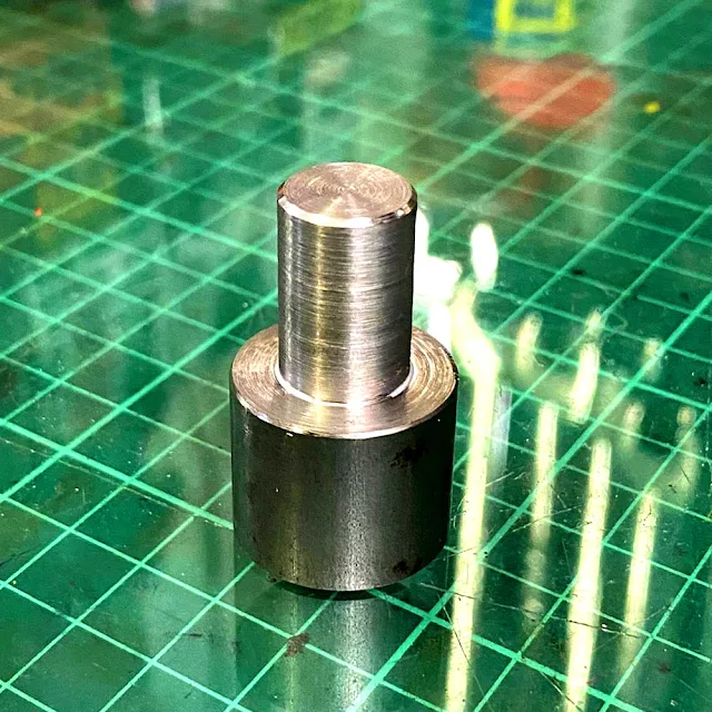 | ||
A drift was fabricated to protect the SP1 pivot bolt from the carnage about to be unleashed.
|
 |
| And the remains of the drifts after the SP1 pivot bolt has been removed. |
Once the swing-arm was out the various bits were examined and measured using a telescopic bore gauge and a Moore & Wright 0-25 mm Micrometer with a resolution of 0.01 mm. That's 1/100th of a millimetre. That's pretty small and at that scale, there is variation in dimension depending on where the dimension is taken, so things have to be averaged out.
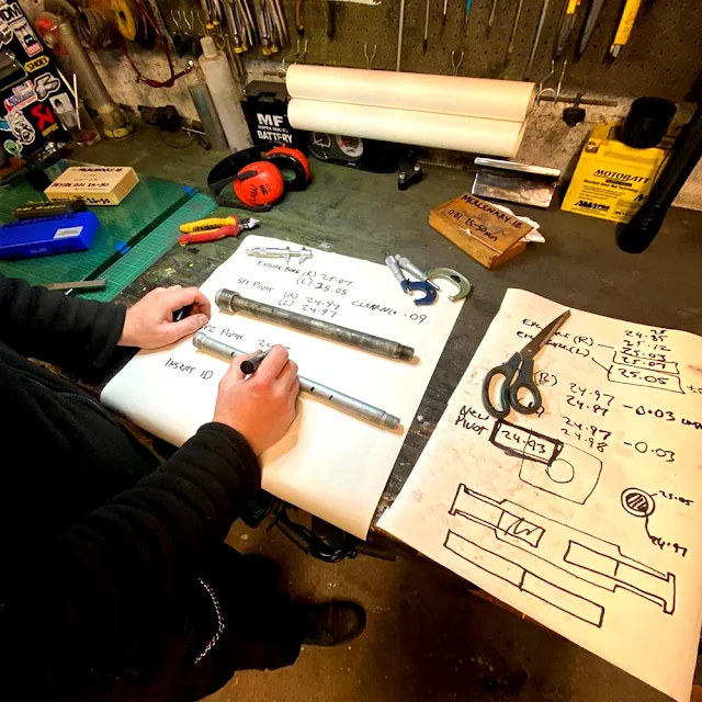 |
| Dimensions and calculations. |
So the nominally 25 mm SP1 pivot averaged out at diameter 24.93 mm.
And the nominally 25 mm bores on either side of the motor came out at diameter 25.03 mm.
This results in a clearance of 0.1 mm - 1/10th of a mm. This, in engineering terms, is a Sliding Fit.
If you think about it, this makes sense. The pivot bolt is tight enough in the bore that it can't rattle about, but it's not so tight that it has to be forced - it should slide in and out without difficulty.
There was something else that turned up in the inspection. The bore in the rear of the motor is not a nominal 25 mm for the whole width. The first 38 mm on either side are machined to a nominal 25 mm, but the middle section is a cast finish, wider by a millimetre or two.
So remember the theories outlined above?
Well, Theory 2 with the flanged sleeves is a bust. Firstly because there is no need for the sleeves to be longer than 38 mm and secondly, although a flange could be used on the left side without problem, fitting a flange on the right side will force the swing-arm off center to the right by the thickness of the flange. And in any case, because the two pieces have to be a press fit which will hold itself in place anyway, the flanges don't really serve a purpose.
And Theory 3 with the single long sleeve? This is fine as far as the theory goes, but with the equipment available, it wasn't possible to make a sleeve 160 mm long with a center bore accurate to 0.01 mm. It is possible to manufacture such a piece, it's just I can't do it in-house.
And there is an easier way...
But first, let's talk about Press Fits. We've already mentioned Sliding Fits and a Press Fit is kind of the opposite of that. A Press fit is when the shaft has a larger diameter than the bore in which it fits. Obviously there are caveats with this. The shaft can't be so big that it will break or permanently deform the part with the hole, and back in the real world, it must be able to be fitted using a realistic amount of force.
So we know the nominally 25 mm bore in the SP1 motor was actually 25.03 mm, so we want a sleeve with an outside diameter that's bigger than this. But by how much?
Fortunately the ISO 286 specification document has your back here...
ISO 286 reveals that a nominally 25 mm shaft, for a press fit has a dimension between 25.022 and 25.035. But this didn't seem right given the actual dimension of the bore, so the outside diameter of the sleeve was upped to 25.07 for an interference fit of about 0.04.
So that's the outside diameter. What about the inside diameter?
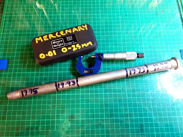 |
| The SP2 pivot bolt showing the differences in diameter. |
Well, the new SP2 sleeve has a nominal diameter of 20 mm, but measuring it revealed a maximum diameter of 19.95.
Remember the clearance of the SP1 pivot in the SP1 bore was 0.1 mm?
And remember that the whole point of this exercise was to reduce the drop in rigidity caused by using the smaller pivot?
It was decided to halve the clearance between the new SP2 pivot and the sleeve to 0.05 mm, which should still provide a Sliding Fit between the pivot and the sleeve. So pivot diameter of 19.95 mm plus clearance of 0.05 mm gives an Inside Diameter of 20.00 mm.
To reiterate this, the SP1 pivot had a clearance of 0.1 mm. That's 0.05 all around. The new clearance for the new SP2 pivot is 0.05 mm. That's 0.025 mm all around.
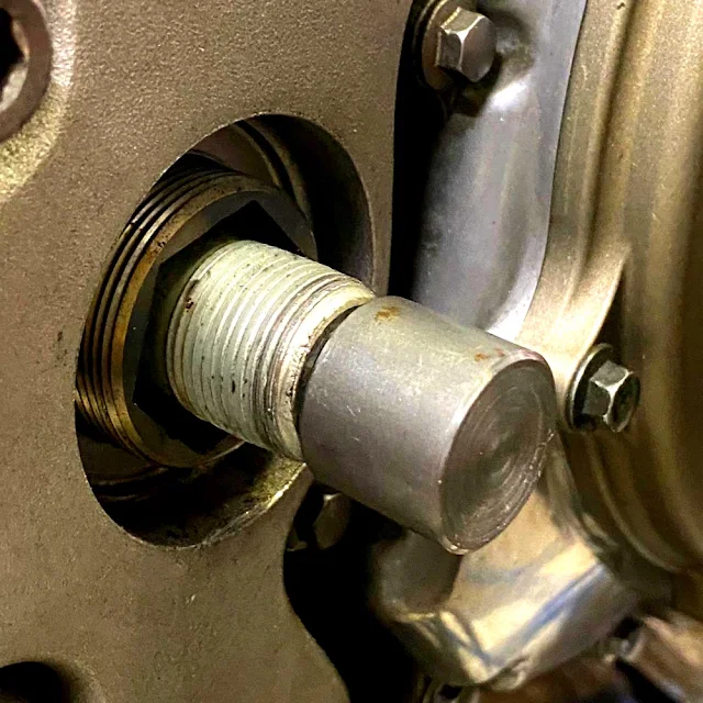
So, two sleeves, OD 25.07 mm, ID 20.00 mm and length 38 mm were turned on the lathe.
 |
| Two sleeves, OD 25.07 mm, ID 20.00 mm and length 38 mm were turned on the lathe. |
So once the sleeves were made, they had to be pressed into the bores in the back of the motor. This was complicated slightly because the motor was still in the frame, and the sleeves had to pass through the holes in the sides of the frame.
 |
| The bores in the back of the motor were heated prior to installation of the sleeves. Conveniently the holes in the frame were a snug fit for the heat-gun. |
In order to install the sleeves in a controlled manner, a tool was fabricated using some M10 threaded bar, some M10 nuts and some parts turned on the lathe to ensure that the sleeves went in straight and only to the depth required.
 |
| A tool was fabricated to install the sleeves in a controlled manner. |
And because here at MERCENARY we believe that if a thing is worth doing, it's worth overdoing, everything was cleaned thoroughly with acetone and Bearing Lock applied to the sleeves and bores. Using the fabricated tool, the installation of the sleeves was simple and uneventful.
 |
| Granville Bearing Fit and Stud Lock. |
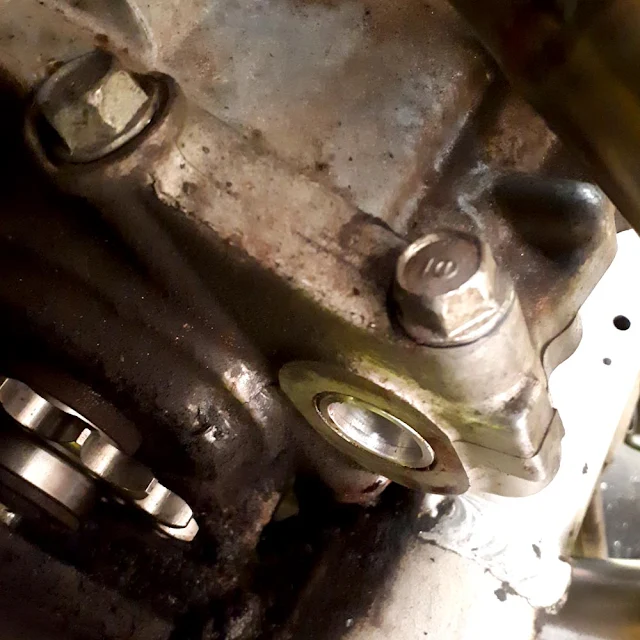 |
| Left sleeve in situ. The sleeve is a press fit in the bore so it can't move, but bearing lock was used because why not. |
 |
| Right Sleeve in situ in the rear of the motor. |
Even though HRC assembled the swingarm dry, at MERCENARY that's not how we roll. Everything was liberally slathered with Copper Anti-seize during reassembly. Reassembly went ahead without difficulty and with only one thing to note. The adjuster nuts that hold the swing-arm into the pivot resemble giant grub-screws and require unusually sized hex head (Allen) drivers. It was found that the outside of 16 mm and 21 mm box wrenches were a good enough fit to be used instead of buying the correct tools from Honda.
 |
| A 16 mm box wrench was used on the SP2 adjusters instead of the obscure Allen key that Honda intended. Note the copper anti-seize paste on the adjuster nut. |
 |
| And a 21 mm box wrench worked on the SP1 adjuster nuts. |
Once the new swing-arm was installed, the bike was fitted with a new 2:1:2 under-seat exhaust system that required some slight modification of the seat unit. It was decided to constrain the modifications to the horizontal parts of the underside of the seat unit rather than modifying the sloped part where the cut outs would be more easily seen. This required the milling of portions of the exhaust hanger washers so as not to put the seat unit under stress.
 |
| The exhaust hanger washers were machined to allow clearance for the bodywork. |
The rest of the reassembly/install went without incident.
 |
| Some lock-wiring. MERCENARY never misses an opportunity to install lock-wire. |
 |
| The SP2 swing-arm with the cut-out to allow fitment of the racing style under-seat exhaust. |
 |
| Look at those curves! Just look at them! |
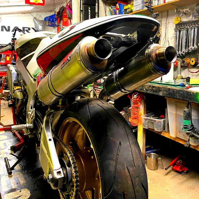 |
| The under-seat exhaust with the bodywork in situ. |
 |
| Tired now. |
*I don't know for a fact that it does and I have no easy, objective way to find out. But it could be done experimentally by holding the head-stock of the frame in a fixture and bolting a long bar into the swing-arm in place of the axle bolt. Then applying a given force to the end of that bar, first with the SP2 components with no sleeves, and then with the sleeves in place and measuring the deflection in the bar for both cases. But that was beyond the scope of this project.
Images Ro and Lunar
#VTR1000SP1 #VTR1000 #SP1 #SP2 #Honda #HondaSP1 #HondaVTR #HondaRC51 #RC51 #SwingArmConversion #SP2SwingArm #Mercenary #MercenaryMotorcycles #MercenaryMotorcycleWorkshop #MercenaryGarage


Excellent work from mercenary garage as usual. You know your bike is in safe hands, I'm speaking from experience here! Apart from the excellent machine shop skills over at mercenary, a lot of thought and figuring out is done before hand, mercenary garage never just bulls into a project. Form and function play a big part in any job undertaken in the workshop, no matter how big or small a job. 👌
ReplyDeleteYou smooth-talkin' bastard!
DeleteDeadly work and I really enjoyed the write-up.
ReplyDeleteWell done that man!
Trev BTW 😉
DeleteFantastic project, I would have
ReplyDeleteGreat confidence in Mercenary, I would think there is a well paid job for you in Japan.
I wish!
DeleteBeautiful work.
ReplyDeleteVery interesting detailed description of the engineering.
Not too over complicated for a lay man such as myself to understand. Not that I'd attempt that myself.
Thanks.
DeleteHopefully this is seen by anyone considering doing the swap. Top job dude
ReplyDeleteIt's many years since I did this conversion, but many (including in this article) are doing it in a way I believe is incorrect.
ReplyDeleteThe sleeve is required so that the entire assembly (frame, Swing-Arm and engine) end up bolted tightly together and 20mm or 25mm pivot bolt is going to make next to no difference to the final rigidity.
It is this sleeve which causes the confusion. Easy enough to manufacture a sleeve of the appropriate size, but that's not the problem. When the assembly is tightly bolted together by the pivot bolt, the sleeve design shown above means that the outer spacer on the LHS is clamped to the engine via only a thin annular ring that contacts the engine cases, around the hole into which the sleeve is fitted. So all the pressure of the pivot bolt relies an a very small contact area and if the cases distort there in any way due to the small area and hence excessive pressure, the entire assembly could become loose.
The RH end is not a problem due to the larger diameter of the outer spacer and the larger contact area that provides against the cases means that is not a concern.
Honda's solution was to use a top-hat shaped sleeve, with a flange at the LH end. This distributes the clamping pressure over a large area around that end of the rear hole at the back of the engine. But the steel sleeve Honda use has to be placed there before the crankcases are bolted together and splitting the cases just for this is impractical. Not only that, it is not available as a spare part.
My solution was to make the same shaped sleeve in Aluminium and of the exact length to match the engine cases. So the top-hat shaped sleeve would slide in from the LHS and the larger area of the flange at that end contacts the cases. In this way it can be inserted into an assembled SP-1 engine, but when the pivot bolt is tight, it forms a solid assembly with all forces evenly distributed and over the larger area of the flange at the LH end and the sleeve compressed from both ends, just as Honda designed.
As I said, it's a long time since I did this, but I keep seeing reports of these conversions being done without a true understanding of what is required. It is NOT just a simple case of making a spacer or spacers to fit as shown here. You have to take into account the diameter of the hole at the back of the cases and that of the LH outer spacer that will be forced up against those cases. The method shown in this article will work, at least for a time, but it's not how Honda intended and I can see how it could cause problems in the future if not done correctly.
Interesting. Thanks for your comment. I hear what you're saying and I'm inclined to agree with you.
ReplyDeleteCan you recall what you did to avoid offsetting the the swingarm by the thickness of the flange?
Not an issue as the SP-2 sleeve has that flange on the left in any case, but in steel. Without that flange the S/A would be offset to the right, so it really needs to be there.
ReplyDeleteA quick solution would be a (steel?) washer of the correct dimensions, placed on the left between the engine and LH S/A spacer. That would save having to manufacture an entirely new sleeve, but trickier to install maybe.
It must be 15 years since I did this and memory is a little hazy, but about to embark on another RVT project and hence saw this while perusing the 'Net for some other info. I have a vague memory of making the sleeve in 2 halves, but that may have been just first idea of top-hat each side until realising what was actually required. Unfortunately I cannot now find my original drawings.
The issue to bear in mind is that the LH spacer is only slightly larger dia. than the whole through the engine so the entire clamping force is applied only to that annular ring which is less than 1mm if memory is correct and that's too much for those cases. It needs the flange (or washer) to spread the load.
Just another thought. If doing this again (I will be), I would make a short top-hat sleeve for the LHS in stainless steel (a tight fit so it doesn't fall out when trying to assemble) and then a straight Aluminium sleeve for the rest of the width of the engine at that point. In this way the stronger steel would better handle the load, while the lighter Al would suffice for the remainder of the sleeve.
ReplyDeleteI previously has such a discussion with Thorsten Durbahn, who also got it wrong.
Apparently cannot edit a post so have to correct first one today. I was intending to type "hole through engine" which ended up as "whole…". Apologies.
ReplyDelete